


Front Wheel Alignment
The alignment process brings the front wheels into parallel (from a bird's-eye view), also known as zero toe, when the handle post is vertical ensuring the longest tire life and the most predictable steering performance.
Required Equipment
- 6 mm Allen (2019 and earlier models will require a 5 mm Allen instead)
- 13 mm socket
- Ratched (for 13 mm socket)
- Tape measure
- Level
Procedures
- Level the Deck - Use a level perpendicular to the length of the deck to ensure the deck is completely flat. Do this with the board resting on a flat and level surface

- Front Measurement - Measure the distance between the outer grooves in the tire tires approximately halfway up the tires at the furthest point forward (22 3/4” below).

For the Elite and Elite Pro, measure between the center grove on the tires.


- Rear Measurement - Repeat the procedure for the rear edge of the tires by measuring under underneath the chassis so that the tape measure is touching the bottom of the chassis (22 5/8” below).

- Compare measurements - Subtract the bigger measurement from the smaller measurement => 22 ¾” - 22 ⅝” = ⅛” (the difference between the front and the rear of the tire ⅛”)
If the difference is less than ¼” or 6 mm then the tires are aligned properly and the alignment process is complete.
If the difference is greater than ¼” or 6 mm then continue to step 5.
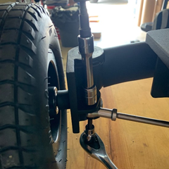
- Remove the Lock Nuts - Remove the lock nuts on either both sides where the tie rod attaches to the wheel pivot with a 13 mm socket (an extension for the socket will make this easier)


- Remove the Steering Linkage Bolt - Remove the steering linkage bolt below the lock nuts removed from above with a 6 mm Allen on both sides (2019 models and older will require a 5 mm hex).

- Tire Rod Adjustment - Rotate the tie rods from the rod ends according to the options below.
If the measurement at the front of the tires was larger than the measurement at the rear of the tires, then loosen the rod end with a 14 mm wrench (counterclockwise) by 1/2 of a revolution, reattach the bolt to the pivot, then repeat on the opposite wheel.
If the measurement at the rear of the tires was larger than the measurement at the front of the tires, then tighten the rod end with a 14 mm wrench (clockwise) by 1/2 of a revolution, reattach the bolt to the pivot, then repeat on the opposite wheel.

If the bolt cannot be removed from the tie rod in the picture above then rotate a full revolution.
- Check the Alignment - With the steering linkage reattached to the wheel pivots on each side, repeat the first 4 steps to check the alignment before continuing to the next step. If the wheels are still not aligned then also complete steps 5-8 again before continuing to next step.
- Tighten the Lock Nuts - Once the alignment is complete use the 6 mm Allen and the 13 mm socket to fully tighten both the wheel bolt and the locknut. Repeat on both sides.
Have more questions? Contact support@cycleboard.com


.jpg)


.svg)


